Documents

No documents found
Инструкции и справка
Quick Start with ROSSMA Wiki ↗
Completion time: 30 minutes
Required: ROSSMA device, LoRaWAN base station[1], access to ROSSMA NETS server
This step-by-step guide will help you quickly start working with ROSSMA devices - from unboxing to receiving first data.
Step 1: Preparation (5 minutes)
What you will need
- ROSSMA device (e.g., ANALOG Ex Single 14 A/h)
- LoRaWAN base station (RAK7289CV2 or similar)
- Access to ROSSMA NETS server
- Sensor for connection (for ANALOG/MODBUS)
- Screwdriver, cable (for installation)
WARNING: ROSSMA devices are equipped with non-rechargeable lithium thionyl chloride battery. Attempting to charge the battery may cause fire!
Find device parameters
Parameters are indicated on the sticker on the housing or in the device datasheet.
Write down:
- DevEUI[2]: 16-digit hex code (e.g.:
70B3D57ED0041234) - AppEUI[3]: 16-digit hex code
- AppKey[4]: 32-digit hex code
Step 2: Network registration (10 minutes)
2.1 Login to ROSSMA NETS
- Open browser and go to your server address
- Login with your credentials
2.2 Create application
Application is a logical group of devices (e.g., "Wells section 1").
- Go to "Applications" section
- Click + Create
- Fill in:
- Name: Name (e.g., "Test devices")
- Description: Description (optional)
- Click Create Application
2.3 Add device
- Open created application
- Go to Devices tab
- Click + Add Device
- Fill in:
- Device name: Name (e.g., "Well 1 Pressure")
- Device EUI: enter DevEUI (without spaces)
- Device profile: select device profile
- Click Add Device
2.4 Configure activation keys
- Go to Keys tab
- Select OTAA[5] (recommended)
- Enter:
- Application EUI: device AppEUI
- Application Key: device AppKey
- Click Save
Device is ready for activation!
Step 3: Installation and connection (10 minutes)
3.1 Device mounting
For ANALOG Ex Single Channel:
- Open housing cover (4 screws)
- Connect sensor to connector (see connection diagram)
- DO NOT CLOSE the cover (for LED indication control)
Detailed installation instructions
3.2 Powering on the device
WARNING: Make sure the device is registered in the network (Step 2) BEFORE powering on.
- Find power jumper
- Install jumper on contacts
- Watch LED indication:
- ACT LED blinked → measurement completed
- LORA LED blinked → data transmitted
Wait: 1-5 minutes until first connection.
3.3 Check connection
- Return to ROSSMA NETS
- Open your device page
- Go to LoRaWAN frames tab
- Check:
- Join Request / Join Accept - device activated
- Uplink data - first data received
Success! Device is connected and transmitting data.
Step 4: View data (5 minutes)
4.1 Open "Device data" tab
- Go to Device data tab
- Check last received data:
- Temperature (built-in sensor)
- Battery voltage
- Sensor readings (for ANALOG - 4-20 mA value)
4.2 Check decoding
Data is automatically decoded by the server.
ANALOG data packet example:
HEX: dd08cb0dbc1500000eb0
Decoded:
{
  "temperature": 21,      // °C
  "voltage": 3.516,       // V
  "adc": 2251,           // ADC value (4-20 mA)
  "uptime": 3760         // seconds
}
Example in ROSSMA NETS interface:
When viewing device data on ROSSMA NETS server, you will see decoded values displayed in a table or graph format with timestamps and signal quality indicators (RSSI[6], SNR[7]).
Step 5: Configuration (optional)
Change transmission interval
Default: once per day. For testing, we recommend setting 10-15 minutes.
- Download ROSSMA Device Configurator
- Connect to ROSSMA NETS server
- Select device
- Change "Communication interval": 15 minutes
- Click Send → Save
Application: Device will apply settings after next connection.
What's next?
Recommended actions
- Close device cover after checking LED indication
- Set optimal interval for your application
- Configure alerts for critical values
- Integrate with SCADA/IoT platform
Useful links
- Device Catalog
- Technical Documentation
- FAQ - Frequently Asked Questions
- Battery Life Calculator
- LoRaWAN Technology
Technical Support
Email: info@rossma.ru
Support: rossma.ru/support
Checklist
Before starting operation, make sure:
- Device is registered in ROSSMA NETS
- Join Accept and first data received
- Sensor is connected correctly
- Signal quality is acceptable (RSSI[6:1] >-120 dBm, SNR[7:1] >-5 dB)
- Transmission interval is configured for your tasks
- Housing cover is closed and tightened
- Device is securely mounted
Done! Your ROSSMA device is working and transmitting data.
Footnotes
LoRaWAN (Long Range Wide Area Network) - wireless communication protocol for IoT devices over long distances with low power consumption. More about LoRaWAN ↩︎
DevEUI (Device Extended Unique Identifier) - unique 64-bit device identifier in LoRaWAN network, similar to MAC address. ↩︎
AppEUI (Application Extended Unique Identifier) - 64-bit application identifier in LoRaWAN network, used for grouping devices. ↩︎
AppKey (Application Key) - 128-bit encryption key for secure device activation via OTAA protocol. ↩︎
OTAA (Over-The-Air Activation) - device activation method in LoRaWAN network with dynamic encryption key exchange. More secure than ABP. ↩︎
RSSI (Received Signal Strength Indicator) - received signal level indicator in dBm. Higher value (closer to 0) means better signal. Acceptable values: from -120 to -70 dBm. ↩︎ ↩︎
SNR (Signal-to-Noise Ratio) - signal-to-noise ratio in dB. Positive values indicate good communication quality. Acceptable values: above -5 dB. ↩︎ ↩︎
Frequently Asked Questions (FAQ) Wiki ↗
Here are answers to the most common questions about ROSSMA devices, their connection, configuration and operation.
General Questions
What is ROSSMA IIOT-AMS?
ROSSMA IIOT-AMS (Automated Monitoring System) is a series of autonomous and non-autonomous meter-switches for wireless data transmission from monitoring and measuring instruments via LoRaWAN and NB-IoT networks.
Which technology to choose: LoRaWAN or NB-IoT?
| Criterion | LoRaWAN | NB-IoT |
|---|---|---|
| Coverage | Own network | Carrier network |
| Range | Up to 15 km | Up to 10 km |
| Battery life | Up to 15 years | Up to 10 years |
| Cost | No subscription fee | Subscription fee |
| Application | Industrial sites | Urban infrastructure |
What is the difference between autonomous and non-autonomous devices?
Autonomous (Stand-alone):
- Powered by built-in battery (14/28/126 A/h)
- Operation without external power up to 15 years
- Explosion-proof version (Ex)
- Application: remote sites, hazardous areas
Non-autonomous (PWR):
- External power 230 V or DC 12-24 V
- Continuous operation
- Smaller housing
- Application: sites with available power supply
Connection and Setup
How to register a device in LoRaWAN network?
Required: DevEUI, AppEUI, AppKey of device (indicated on housing or in datasheet)
Registration steps:
- Login to LoRaWAN server control panel (ROSSMA NETS)
- Create new application or select existing one
- Add device:
- Activation type: OTAA (recommended) or ABP
- Enter DevEUI, AppEUI, AppKey
- Power on device (install power jumper)
- Wait for first message (usually within 2-5 minutes)
Device does not appear in network after registration
Check:
- Power jumper is installed
- Battery is charged (>3.3 V)
- DevEUI, AppEUI, AppKey entered correctly
- Correct frequency plan selected (RU864 for Russia)
- LoRaWAN base station is in range
TIP: Use ROSSMA Configurator to check signal quality.
If problem persists:
- Check device LED indication (ACT/LORA/ERR)
- Reboot device (RESET button)
- Make sure base station is connected to server
How to activate device in NB-IoT network?
Required: Carrier SIM card with activated NB-IoT tariff
Activation steps:
- Install SIM card in device slot
- Make sure SIM card is active and has balance
- Power on device
- Device will automatically register in carrier network (3-10 minutes)
- Configure APN parameters in Configurator
Supported carriers:
- MegaFon
- MTS
- Beeline
- Tele2
Device does not register in NB-IoT network
Error indication:
| NET LED | Problem | Solution |
|---|---|---|
| Not lit | SIM card not detected | Check SIM installation |
| Fast blink (1/sec) | Searching network | Wait 5-10 minutes |
| Slow blink (3 times - pause) | No registration | Check carrier coverage |
| Constantly lit | Registered | Normal |
WARNING: NB-IoT requires good carrier network coverage. For remote locations, LoRaWAN is recommended.
Operation
How to increase battery life?
Main factor: data transmission interval
Increasing interval from 1 minute to 1 hour extends 14 A/h battery life from 90 days to 3+ years.
Recommendations:
-
Set optimal transmission interval:
- Critical parameters: 5-15 minutes
- Monitoring: 1 hour
- Statistics: 4-24 hours
-
Use battery life calculator for calculation
-
If frequent transmission is needed:
- Choose device with 28/126 A/h battery
- Use external power (DC 3.3V or 220V)
Device technical specifications
How to check battery charge?
Method 1: Via Configurator
- Open ROSSMA Device Configurator
- Connect to network server
- Select device
- Battery voltage is displayed in "General settings" section
Method 2: In last message
Battery voltage is transmitted in every message from device.
Critical values:
- Normal: >3.3 V
- Low charge: 3.0-3.3 V (replace battery within a month)
- Critical:
.0 V (replace immediately)
When to replace battery?
Scheduled replacement:
- Use battery life calculator
- Replace before full discharge (at voltage ~3.2 V)
Unscheduled replacement when:
- Voltage .0 V
- Device stopped connecting
- Unstable operation (missing messages)
IMPORTANT: Use only original FANSO batteries (14/28/126 A/h) or equivalents with similar specifications.
How to change data transmission interval?
Required: ROSSMA Device Configurator
Steps:
- Open Configurator and connect to server
- Select device from list
- Go to "General settings" section
- Change "Communication interval" parameter
- Click "Send" → "Save"
WARNING: Device will apply new settings after next connection (within current interval).
Recommended intervals:
| Application | Interval | 14 A/h battery life |
|---|---|---|
| Emergency alarm | 1-5 minutes | 90-200 days |
| Parameter monitoring | 10-30 minutes | 300 days - 2 years |
| Statistics collection | 1-4 hours | 3-5 years |
| Rare monitoring | 12-24 hours | 5-10 years |
Diagnostics and Troubleshooting
What does LED indication mean?
Battery-powered devices (ANALOG Ex, ESD, VPM)
| LED | Behavior | Meaning |
|---|---|---|
| ACT | Short flash | Sensor trigger / measurement |
| LORA | Short flash | Sending data via LoRaWAN |
| LORA | Double flash | Receiving data from network |
| (no indication) | - | Normal (in sleep mode) |
Externally powered devices (MODBUS, ANALOG non-Ex)
| LED | Behavior | Meaning |
|---|---|---|
| PWR | Constantly lit | Power supplied |
| ACT | Periodically blinks | Data exchange with sensor |
| LORA | Periodically blinks | Data transmission |
| ERR | 1/sec | Communication module not detected |
| ERR | 3 times - pause | No network registration |
| ERR | 5 times - pause | Server send error |
| NET (NB-IoT) | Lit | Registered in carrier network |
| Success (NB-IoT) | Flash | Successful data transmission |
Device does not connect
Diagnostics:
-
Check power:
- Battery: jumper installed, voltage >3.0 V
- External: PWR LED lit
-
Check indication:
- ERR LED blinking? → See table above
- No indication? → Check power
-
Check network registration:
- LoRaWAN: DevEUI, AppEUI, AppKey correct?
- NB-IoT: SIM card active, coverage available?
-
Check signal quality:
- Use Configurator
- RSSI >-120 dBm, SNR >-5 dB
If nothing helps: Contact technical support
Data is not updating
Possible causes:
-
Device is working but data is outdated:
- Check transmission interval settings
- Device may be in power-saving mode
-
Device sends data but it doesn't reach application:
- Check decoder settings on server
- Check platform integration
-
Sensor readings are not changing:
- Check sensor connection to device
- Check MODBUS port/address settings
VPM device (Valve) calibration error
Indication after calibration:
| Indication | Meaning | Solution |
|---|---|---|
| 1 long flash | Success | Calibration completed |
| 10 short + 2 long | Turn error | Repeat calibration |
| 10 short + 3 long | No turns | Check connection |
Error causes:
- Valve not fully open/closed
- Calibration jumper installed incorrectly
- Device not mounted on valve
- Battery discharged (.0 V)
Detailed calibration instructions
Parameter Configuration
How to configure MODBUS parameters?
For ROSSMA IIOT-AMS MODBUS devices:
- Open Configurator
- Select device
- Go to "Custom Modbus profile setup"
- Configure parameters:
- Slave device address
- Baud rate
- MODBUS function (03 Read Holding Registers / 04 Read Input Registers)
- Starting register address
- Number of registers
- Save settings
How to configure alerts and notifications?
Via ROSSMA NETS server:
- Open application page
- Go to "Integrations" tab
- Select integration type:
- Telegram
- HTTP Webhook
- MQTT
- Configure trigger conditions:
- Threshold exceeded
- Connection loss
- Low battery
- Save settings
Alert examples:
- Pressure >100 bar → Email to dispatcher
- Battery .0 V → Telegram notification
- No connection >24 hours → HTTP webhook to SCADA
Technical Support
How to contact technical support?
Email: info@rossma.ru
Phone: +7 342 233 93 99 (weekdays 9:00-18:00 MSK)
Website: rossma.ru/support
When contacting, please specify:
- Device model (e.g., ROSSMA IIOT-AMS ANALOG Ex Single Channel 14 A/h)
- Device DevEUI
- Problem description
- LED indication
Where to download documentation?
"Technical Documentation" section
Available:
- User manuals (PDF)
- Device datasheets
- Setup instructions
- Additional materials
Where to download software?
How to get firmware update?
Firmware update is performed remotely via LoRaWAN/NB-IoT network.
Steps:
- Make sure device is online
- Download firmware file from ROSSMA website
- Upload to Configurator
- Select device and click "Update firmware"
- Wait for completion (5-30 minutes depending on size)
Important:
- Battery must be >3.3 V
- Device must be online
- Do not interrupt update process
Integration
How to get data via API?
ROSSMA NETS provides REST API and MQTT.
# Get latest device data
curl -X GET "https://your-server/api/devices/70B3D57ED0041234/data"
  -H "Authorization: Bearer YOUR_API_KEY"

# Get history for period
curl -X GET "https://your-server/api/devices/70B3D57ED0041234/data?from=2025-01-01&to=2025-01-31"
  -H "Authorization: Bearer YOUR_API_KEY"
import requests
from datetime import datetime, timedelta

API_URL = "https://your-server/api/devices"
API_KEY = "YOUR_API_KEY"
DEV_EUI = "70B3D57ED0041234"

headers = {"Authorization": f"Bearer {API_KEY}"}

# Latest data
response = requests.get(f"{API_URL}/{DEV_EUI}/data", headers=headers)
data = response.json()

# History for last 7 days
params = {
    "from": (datetime.now() - timedelta(days=7)).isoformat(),
    "to": datetime.now().isoformat()
}
history = requests.get(f"{API_URL}/{DEV_EUI}/data", headers=headers, params=params)
const API_URL = 'https://your-server/api/devices';
const API_KEY = 'YOUR_API_KEY';
const DEV_EUI = '70B3D57ED0041234';

// Async/Await version
async function getDeviceData() {
  const response = await fetch(`${API_URL}/${DEV_EUI}/data`, {
    headers: { 'Authorization': `Bearer ${API_KEY}` }
  });
  return await response.json();
}

// Usage
const data = await getDeviceData();
console.log(`Temperature: ${data.temperature}°C`);
<?php
$apiUrl = "https://your-server/api/devices";
$apiKey = "YOUR_API_KEY";
$devEui = "70B3D57ED0041234";

$ch = curl_init();
curl_setopt_array($ch, [
    CURLOPT_URL => "$apiUrl/$devEui/data",
    CURLOPT_RETURNTRANSFER => true,
    CURLOPT_HTTPHEADER => [
        "Authorization: Bearer $apiKey",
        "Content-Type: application/json"
    ]
]);

$response = curl_exec($ch);
$data = json_decode($response, true);

echo "Temperature: " . $data['temperature'] . "°Cn";
echo "Battery: " . $data['battery'] . " Vn";
?>
package main

import (
    "encoding/json"
    "fmt"
    "net/http"
)

type DeviceData struct {
    Temperature float64 `json:"temperature"`
    Battery     float64 `json:"battery"`
    AnalogValue float64 `json:"analog_value"`
}

func main() {
    apiURL := "https://your-server/api/devices/70B3D57ED0041234/data"

    req, _ := http.NewRequest("GET", apiURL, nil)
    req.Header.Set("Authorization", "Bearer YOUR_API_KEY")

    client := &http.Client{}
    resp, _ := client.Do(req)
    defer resp.Body.Close()

    var data DeviceData
    json.NewDecoder(resp.Body).Decode(&data)

    fmt.Printf("Temperature: %.1f°Cn", data.Temperature)
}
How to integrate with SCADA?
Available protocols: MQTT (recommended), HTTP REST API, OPC UA, Modbus TCP
const mqtt = require('mqtt');

const client = mqtt.connect('mqtt://your-server:1883', {
  username: 'your-username',
  password: 'your-password'
});

// Subscribe to all application devices
client.subscribe('application/+/device/+/rx');

client.on('message', (topic, message) => {
  const data = JSON.parse(message.toString());
  console.log('DevEUI:', data.deviceEUI);
  console.log('Data:', data.object);

  // Send to SCADA
  sendToScada(data);
});
import paho.mqtt.client as mqtt
import json

def on_message(client, userdata, msg):
    data = json.loads(msg.payload.decode())
    print(f"DevEUI: {data['deviceEUI']}")
    print(f"Temperature: {data['object']['temperature']}°C")

client = mqtt.Client()
client.username_pw_set("your-username", "your-password")
client.on_message = on_message

client.connect("your-server", 1883, 60)
client.subscribe("application/+/device/+/rx")
client.loop_forever()
using MQTTnet;
using MQTTnet.Client;

var factory = new MqttFactory();
var client = factory.CreateMqttClient();

var options = new MqttClientOptionsBuilder()
    .WithTcpServer("your-server", 1883)
    .WithCredentials("your-username", "your-password")
    .Build();

client.ApplicationMessageReceivedAsync += e =>
{
    var payload = Encoding.UTF8.GetString(e.ApplicationMessage.PayloadSegment);
    var data = JsonSerializer.Deserialize<DeviceMessage>(payload);
    Console.WriteLine($"Received data: {data.Object.Temperature}°C");
    return Task.CompletedTask;
};

await client.ConnectAsync(options);
await client.SubscribeAsync("application/+/device/+/rx");
How to configure Webhook?
In ROSSMA NETS:
- Go to Application → Integrations
- Add HTTP Integration
- Specify your server URL
- Select events (uplink, downlink, join)
- Save
const express = require('express');
const app = express();

app.use(express.json());

app.post('/webhook/rossma', (req, res) => {
  const { deviceEUI, data, timestamp } = req.body;

  console.log(`[${timestamp}] Device ${deviceEUI}:`);
  console.log(`  Temperature: ${data.temperature}°C`);
  console.log(`  Battery: ${data.battery} V`);

  // Save to DB, send alerts, etc.
  processDeviceData(deviceEUI, data);

  res.status(200).send('OK');
});

app.listen(3000);
from flask import Flask, request, jsonify

app = Flask(__name__)

@app.route('/webhook/rossma', methods=['POST'])
def handle_webhook():
    payload = request.json

    device_eui = payload['deviceEUI']
    data = payload['data']
    timestamp = payload['timestamp']

    print(f"[{timestamp}] Device {device_eui}:")
    print(f"  Temperature: {data['temperature']}°C")
    print(f"  Battery: {data['battery']} V")

    # Process data
    process_device_data(device_eui, data)

    return jsonify({'status': 'ok'}), 200

if __name__ == '__main__':
    app.run(port=3000)
<?php
// webhook.php
$payload = json_decode(file_get_contents('php://input'), true);

$deviceEUI = $payload['deviceEUI'];
$data = $payload['data'];
$timestamp = $payload['timestamp'];

error_log("[$timestamp] Device $deviceEUI:");
error_log("  Temperature: {$data['temperature']}°C");
error_log("  Battery: {$data['battery']} V");

// Save to database
$pdo = new PDO('mysql:host=localhost;dbname=iot', 'user', 'pass');
$stmt = $pdo->prepare("INSERT INTO measurements (device_eui, temperature, battery, timestamp) VALUES (?, ?, ?, ?)");
$stmt->execute([$deviceEUI, $data['temperature'], $data['battery'], $timestamp]);

http_response_code(200);
echo json_encode(['status' => 'ok']);
?>
Example Webhook payload:
{
  "deviceEUI": "70B3D57ED0041234",
  "applicationID": "1",
  "data": {
    "temperature": 23.5,
    "battery": 3.58,
    "analog_value": 12.4
  },
  "rxInfo": {
    "rssi": -85,
    "snr": 8.5,
    "gatewayID": "B827EBFFFE123456"
  },
  "timestamp": "2025-12-09T14:30:00Z"
}
Didn't find answer to your question?
LoRaWAN Technology Wiki ↗
In the era of the Internet of Things (IoT), more and more devices require wireless connectivity to transmit data over long distances with minimal power consumption. One of the key technologies meeting these requirements is LoRaWAN (Long Range Wide Area Network).
What is LoRaWAN?
LoRaWAN is a communication protocol designed for organizing energy-efficient networks with large coverage areas. It is intended for devices that transmit small amounts of data over long distances.
Main advantages of LoRaWAN:
- Communication range: up to 45 km in open terrain and up to 10 km in urban environments.
- Low power consumption: devices can operate on battery power for up to 10 years. Calculator
- Scalability: network supports connection of thousands of devices.
- Security: data is encrypted at both network and application levels.
LoRaWAN Network Architecture
Network components:
- End devices (sensors, ROSSMA meters)
- Gateways (LoRaWAN base stations)
- Network server (ROSSMA NETS)
- Application server (user applications)
LoRaWAN Device Classes
LoRaWAN defines two main device classes with different operating modes:
ROSSMA devices support Classes A and C:
- Class A: battery-powered sensors with autonomous operation up to 10 years
- Class C: mains-powered devices for continuous monitoring
Class comparison:
| Parameter | Class A | Class C |
|---|---|---|
| Power consumption | Minimal | High |
| Receive windows | After transmission | Continuous |
| Downlink latency | High | Minimal |
| Application | ROSSMA battery sensors | ROSSMA mains-powered devices |
LoRa Physical Layer
LoRa uses CSS (Chirp Spread Spectrum) modulation method, providing high resistance to interference and communication range up to 45 km in line of sight. Adaptive data rate allows optimizing the balance between range and power consumption.
LoRaWAN Network Deployment in Russia
LoRaWAN is actively developing in Russia, however network deployment requires consideration of regulatory requirements and frequency regulation specifics. In particular, since July 1, 2024, Russia has adopted GOST R 71168-2023 "Information technologies. Internet of Things. LoRaWAN RU specification", which defines requirements for LoRaWAN equipment and networks.
LoRaWAN RU
In Russia, frequencies in the 863–870 MHz range are allocated for LoRaWAN operation, which belongs to the RU864 band. This band is permitted for unlicensed use, making it convenient for IoT network deployment.
RU864 Frequency Plan Structure
RU864 Frequency Channels:
Main channels (Join requests):
| № | MHz | kHz | DR | DC | Power |
|---|---|---|---|---|---|
| 1 | 868.9 | 125 | 0-5 | <10% | 25 mW |
| 2 | 869.1 | 125 | 0-5 | <10% | 25 mW |
📋 Additional channels (15 channels) — click to expand
| № | MHz | kHz | DR | DC | Power |
|---|---|---|---|---|---|
| 3 | 864.1 | 125 | 0-5 | 0.1% | 25 mW |
| 4 | 864.3 | 125 | 0-5 | 0.1% | 25 mW |
| 5 | 864.5 | 125 | 0-5 | 0.1% | 25 mW |
| 6 | 864.7 | 125 | 0-5 | 0.1% | 25 mW |
| 7 | 864.9 | 125 | 0-5 | 0.1% | 25 mW |
| 8 | 866.1 | 125 | 0-5 | 1% | 25 mW |
| 9 | 866.3 | 125 | 0-5 | 1% | 25 mW |
| 10 | 866.5 | 125 | 0-5 | 1% | 25 mW |
| 11 | 866.7 | 125 | 0-5 | 1% | 25 mW |
| 12 | 866.9 | 125 | 0-5 | 1% | 25 mW |
| 13 | 867.1 | 125 | 0-5 | 1% | 25 mW |
| 14 | 867.3 | 125 | 0-5 | 1% | 25 mW |
| 15 | 867.5 | 125 | 0-5 | 1% | 25 mW |
| 16 | 867.7 | 125 | 0-5 | 1% | 25 mW |
| 17 | 867.9 | 125 | 0-5 | 1% | 25 mW |
Note: For channels 3-7, DC 0.1% or LBT is used; for channels 8-17, DC 1% or LBT
RU864 Key Features:
- Main channels (1-2): used for Join requests and initial connection
- Additional channels (3-17): configured dynamically by network server
- LBT (Listen Before Talk): channel listening before transmission to avoid collisions
- Duty Cycle: transmission time limitation for regulatory compliance
- Channel spacing: 0.2 MHz between adjacent channels
Additional Materials
Related pages:
- LoRaWAN Mesh Networks — relay and border gateways for coverage extension up to 100+ km
- ROSSMA System Architecture — complete IIoT platform architecture
- Quick Start — connecting devices to ROSSMA NETS
- Device Catalog — ROSSMA equipment lineup
ROSSMA System Architecture Wiki ↗
ROSSMA (LLC "Development of Equipment for Communication Systems, Metrology and Automation") is a Russian developer and manufacturer of IoT/IIoT equipment.
Mission: To make automation simpler, easier and more accessible.
Key advantages:
- Battery life up to 10 years (LoRaWAN)
- Service life up to 20 years
- Coverage range up to 45 km
- Low cost of ownership (several times cheaper than GSM/WiFi solutions)
- Unlicensed 868 MHz band (no subscription fee)
- Proprietary ROSSMA IIoT-AMS platform
LPWAN Technologies
ROSSMA uses LPWAN (Low-Power Wide-Area Network) technologies for wireless data transmission:
Technology Comparison
| Parameter | LoRaWAN | NB-IoT |
|---|---|---|
| Spectrum | Unlicensed (868 MHz) | Licensed (carrier networks) |
| Range | up to 45 km | up to 10 km |
| Speed | 0.3–15 Kbps | up to 150 Kbps |
| Battery life | up to 20 years | up to 10 years |
| Subscription fee | No | Yes |
| Network | Own | Carrier |
| Application | Remote sites | Urban infrastructure |
LPWAN Advantages over GSM/WiFi/ZigBee
- Long range — up to 45 km in open terrain
- Low power consumption — battery operation for years
- High penetration — 868 MHz signal passes through obstacles better
- Scalability — thousands of devices per base station
- Low cost — several times cheaper than GSM/WiFi solutions
ROSSMA Technology Stack
| Component | Technologies |
|---|---|
| Firmware | C, C++, Assembler (IAR Embedded Workbench, Keil MDK) |
| ROSSMA NETS Server | PostgreSQL, Redis, MQTT Mosquitto |
| Configurator | Desktop application |
| Monitoring | Python |
ROSSMA Architecture Deployment Diagram
ROSSMA IIoT-AMS system deployment represents a distributed architecture for industrial Internet of Things:
Use Case Diagrams: Usage Scenarios
Use Case 1: Well Pressure Monitoring
Use Case 2: Valve Control
Use Case 3: Modbus Device Polling
Integration Scenarios
Use Case 4: Corporate System Integration
System Operation Sequence
Sequence Diagram: Data Transmission
Network Topology
Component Diagram: ROSSMA NETS Components
Physical Topology
ROSSMA Equipment Lineup
Meter-Switches
| Device | Description | Application |
|---|---|---|
| IIOT-AMS ANALOG Ex | Single-channel/multi-channel (X4) 4-20mA meter | Pressure, level, temperature sensors |
| IIOT-AMS P-METER | Autonomous wireless pressure transducer | Direct pressure measurement |
| IIOT-AMS MODBUS | Modbus RTU device polling | Meters, analyzers, PLCs |
| IIOT-AMS 1-Wire Ex | Temperature sensor | Temperature monitoring |
Control and Security
| Device | Description | Application |
|---|---|---|
| IIOT-AMS VPM | Valve position sensor | Valve, tap control |
| IIOT-AMS ESD | Equipment security device | Emergency alarm |
| IIOT-AMS Dry Contact | Dry contact control | Security alarm |
| IIOT-AMS Pulse | Pulse counter | Flow meters, counters |
| IIOT-AMS Leak Detector | Leak detector | Pipelines, tanks |
| IIOT-AMS TILT COUNTER Ex | Tilt sensor | Position control |
Software
| Software | Description |
|---|---|
| ROSSMA IIOT-NETS | LoRaWAN network server with web interface |
| IIOT-AMS Device Configurator | Remote device configuration software |
Infrastructure
| Equipment | Description |
|---|---|
| VEGA 2.2 Base Station | Russian-made LoRaWAN gateway |
| RAK 7289CV2 | Industrial LoRaWAN gateway |
| Autonomous Power Kit | Solar panels + batteries for BS |
ROSSMA IIoT-AMS Solution
ROSSMA IIoT-AMS is a universal autonomous wireless meter-switch for controllers and sensors with digital and analog outputs based on LoRaWAN and NB-IoT technologies.
Supported Interfaces
| Type | Interfaces |
|---|---|
| Digital | RS-485, RS-422, RS-232, MODBUS RTU |
| Analog current | 4-20 mA, 0-20 mA, 0-5 mA |
| Analog voltage | 0-0.01 V, 0-1 V, 0-10 V |
| Discrete | Pulse outputs, dry contacts |
Key Capabilities
- Connect up to 8 sensors or 64 controllers simultaneously
- Transmit up to 64 parameters in one data packet
- Battery life up to 10 years (confirmed by field tests)
- Data accumulation when communication is lost
- Emergency event processing
- Internal clock synchronization
Confirmed Autonomous Operation Times
| Measurement interval | Battery operation time |
|---|---|
| Once every 2 minutes | ~6 months |
| Once per hour | ~3 years |
| Once per day | up to 10 years |
Application Areas
Additional Information
LoRaWAN Mesh for ROSSMA Devices Wiki ↗
Traditional LoRaWAN networks use a star topology where all devices connect directly to a single gateway. However, in remote industrial sites where distances exceed 15-20 km and operator infrastructure is absent, this approach is inefficient. LoRaWAN Mesh technology solves this problem by creating a self-organizing network of relay stations, providing connectivity over distances up to 100+ km without external infrastructure. ROSSMA IIOT-AMS devices support mesh network operation, ensuring reliable data transmission over long distances.
What is a Mesh Network?
Mesh network — a topology where each node can receive and relay data from other nodes, creating multiple paths for information transmission. Unlike classic LoRaWAN (star topology), where the failure of a central gateway leads to loss of connectivity with all devices, a mesh network continues operating even when individual nodes fail.
LoRaWAN Mesh — self-organizing base station network technology where data from industrial devices is transmitted through multiple relay nodes to a central server, providing coverage over 100+ km distances. ROSSMA IIOT-AMS devices are compatible with LoRaWAN Mesh, supporting reliable data transmission through Relay and Border Base Stations.
Topology Comparison
Key LoRaWAN Mesh Advantages:
- Extended coverage: from 15 km (LoRaWAN) to 100+ km (LoRaWAN Mesh)
- Fault tolerance: automatic route switching when nodes fail
- Scalability: adding new nodes without network reconfiguration
- Autonomy: operation without telecom operator infrastructure
LoRaWAN Mesh Network Components
ROSSMA Devices
End devices (sensors, meters) are data sources in the mesh network. They operate using standard LoRaWAN protocol and support classes A and C, providing up to 10 years autonomy from a single battery.
| Device | Purpose | Mesh Role | Autonomy |
|---|---|---|---|
| ANALOG Ex | 4-20mA meter | End device | Up to 10 years |
| ANALOG X4 | 4x 4-20mA meter | End device | Up to 10 years |
| MODBUS | Modbus device polling | End device | 5-7 years |
| VPM | Valve control | End device | Up to 10 years |
| ESD | Emergency signaling | End device | Up to 10 years |
End devices are not aware of mesh topology — they operate as regular LoRaWAN devices. Routing happens automatically at the base station level.
Full catalog: ROSSMA Devices
Relay Base Station (RBS)
RBS (Relay Base Station) — a base station that receives signals from ROSSMA devices and other RBS, relays them to border stations or further through the mesh network. Can operate autonomously without internet connection, forming a distributed network over large distances.
Key RBS feature: autonomous operation on solar panels and batteries, enabling network deployment in locations without power grids.
RBS Functions:
- Receiving data from ROSSMA devices (LoRaWAN uplink)
- Receiving data from neighboring RBS (mesh routing)
- Relaying data to other RBS or PBS
- Packet buffering during temporary connectivity loss
- Automatic optimal route selection
- Time synchronization (GPS/GLONASS)
RBS Technical Specifications:
| Parameter | Value |
|---|---|
| Range | Up to 45 km (line of sight) |
| Number of devices | Up to 1000+ per RBS |
| Number of neighbors | Up to 8 other RBS (mesh) |
| Power supply | 12-24V DC, solar panels + battery |
| Protocol | LoRaWAN + proprietary mesh |
| Frequency | 868 MHz (RU864) |
| Power consumption | 5-10W (avg), 2W (standby) |
| Protection class | IP67 (outdoor installation) |
How does RBS routing work?
RBS uses adaptive algorithm:
- Neighbor discovery via beacon packets (RSSI, SNR)
- Building routing table with quality metrics
- Optimal route selection based on hops, signal and load
- Redundancy: up to 3 alternative routes
- Buffering: up to 10,000 packets on connectivity loss
Border Base Station (PBS)
PBS (Border Base Station) — a base station at the mesh network edge that transmits aggregated data from all RBS to server infrastructure via internet. PBS serves as a gateway between the distributed mesh network and centralized ROSSMA NETS server.
PBS connects to the internet via operator tower (AMS) or enterprise network (IIoT), ensuring data delivery to cloud or on-premise server.
PBS Functions:
- Receiving data from RBS via mesh channels
- Data aggregation and buffering
- Transmission to ROSSMA NETS via IP networks (Ethernet, 4G/LTE, GPRS)
- Time synchronization for entire mesh network
- Remote RBS configuration and monitoring
PBS Technical Specifications:
| Parameter | Value |
|---|---|
| Incoming channels | Mesh network (from RBS), LoRaWAN (from devices) |
| Outgoing channels | Ethernet, 4G/LTE, GPRS |
| Protocols | LoRaWAN, Mesh, MQTT, HTTPS, Modbus TCP |
| Buffering | Up to 100,000 packets |
| Synchronization | GPS/GLONASS, NTP |
| Power supply | 220V AC / 12-24V DC |
| Protection class | IP67 (outdoor installation) |
PBS Connection:
- To operator tower (AMS): via 4G/LTE modem, using carrier network
- To enterprise network (IIoT): via Ethernet, using local factory/facility network
LoRaWAN Mesh Network Topology
Typical LoRaWAN Mesh network topology with ROSSMA devices includes several zones:

Figure 1. ROSSMA IIOT network topology with Mesh Gateway
Network Structure:
- Device zone: ROSSMA sensors and meters connected to nearest RBS
- Relay zone: RBS mesh network with multiple routes between nodes
- Border zone: PBS as gateway between mesh network and internet
- Connection zone: operator tower (AMS) or enterprise network (IIoT)
- Monitoring zone: ROSSMA NETS systems for network and device management
Data Transmission Scheme
Typical sequence of data transmission from device to server:
Data path:
ROSSMA Device → RBS 1 (LoRaWAN, 868 MHz) → RBS 2 (Mesh) → RBS N (Mesh) →
PBS (aggregation) → Operator Tower (4G/Ethernet) → ROSSMA NETS (decryption, storage) →
Client Application (REST API/MQTT)
Packet delivery time depends on number of hops:
- 1 RBS: 2-5 seconds
- 3 RBS: 10-20 seconds
- 5 RBS: 30-60 seconds
Mesh Advantages for IIoT
1. Extended Coverage
LoRaWAN Mesh extends operating range from 15 km (single gateway) to 100+ km (RBS chain), covering remote areas without operator infrastructure.
Coverage calculation:
Coverage = Number of RBS × 40 km (average distance between RBS)
Example: 3 RBS × 40 km = 120 km
2. Fault Tolerance
When one RBS fails, the network automatically rebuilds routes through neighboring stations. Data is buffered and sent after connectivity restoration.
Fault tolerance mechanism:
- Each RBS stores up to 3 alternative routes
- On primary route failure, traffic automatically switches to backup
- Data is saved to buffer (up to 10,000 packets) until connectivity restoration
- Backup route switching time: 5-10 minutes
Self-healing: LoRaWAN Mesh automatically adapts to topology changes, detecting new nodes and bypassing failed ones.
3. Scalability
Adding new RBS doesn't require reconfiguring existing network — nodes automatically discover each other and exchange routing tables.
Network scale:
- Up to 10,000+ devices in one mesh network
- Up to 50+ RBS in one cluster
- Up to 5 PBS for redundancy
4. Autonomy
RBS operate on solar panels (50-100W) and batteries (100-200Ah), providing independence from power grids. Typical autonomy: 7 days without sun (winter), unlimited (summer).
5. Cost Efficiency
Mesh topology reduces the number of expensive PBS with internet connection:
| Parameter | LoRaWAN | LoRaWAN Mesh |
|---|---|---|
| Coverage | 15 km | 100 km |
| Internet connection points | 1 per 15 km (5-7 PBS) | 1 per 100 km (1 PBS) |
| Infrastructure cost | ~$10,000 | ~$4,700 |
| Savings | — | 53% |
| Fault tolerance | Low | High |
| Deployment complexity | Low | Medium |
ROSSMA Device Use Cases in LoRaWAN Mesh
Oil & Gas Industry
Task: Monitoring 50 wells across an 80 km area without operator infrastructure
Solution:
- 50 ANALOG Ex devices (pressure, temperature measurement)
- 4 RBS (20 km spacing between nodes: 20 km, 40 km, 60 km, 80 km)
- 1 PBS at control base (0 km) with 4G/LTE connection
Network topology:
- Cluster 1 (0-20 km): wells 1-10 → RBS 1 (20 km)
- Cluster 2 (20-40 km): wells 11-20 → RBS 2 (40 km)
- Cluster 3 (40-60 km): wells 21-30 → RBS 3 (60 km)
- Cluster 4 (60-80 km): wells 31-50 → RBS 4 (80 km)
- Mesh route: RBS 4 → RBS 3 → RBS 2 → RBS 1 → PBS → ROSSMA NETS
Other Applications
Pipeline Transport (200 km):
- 100 devices (VPM for valves, ANALOG for pressure, ESD for leaks)
- 12 RBS along pipeline, 2 PBS (start and end) for redundancy
- Fault tolerance: data flows both ways
Remote Settlements:
- Utility metering in villages without internet
- 1 RBS in village center, PBS at nearest operator tower
- Automated metering without cable laying
LoRaWAN Mesh Network Deployment
Network Planning
Main steps:
- Define coverage area boundaries and calculate number of RBS:
(Distance / 40 km) + 1 - Select RBS installation locations (topography, line of sight)
- Assess power supply (power grid or solar panels)
- Plan backup routes (minimum 2 paths to PBS)
- Determine PBS connection points (operator tower or enterprise network)
Installation and Configuration
Deployment steps:
-
PBS Installation:
- Mount antennas at 10-15m height (tower, building roof)
- Connect to internet (Ethernet or 4G/LTE)
- Configure ROSSMA NETS connection (MQTT/HTTPS)
- Time synchronization (GPS/NTP)
-
RBS Installation:
- Mount antennas at 10-15m height
- Connect power (220V AC or solar panels + battery)
- Register in ROSSMA NETS (via PBS)
- Check connectivity with neighboring RBS (visualization in ROSSMA NETS)
-
Device Registration:
- Add devices in ROSSMA NETS application
- Test connectivity (uplink/downlink)
- Verify routes (packet tracing)
Typical deployment timeline (100 km project with 5 RBS and 100 devices):
| Stage | Duration |
|---|---|
| Site survey and network design | 8 days |
| PBS installation | 2 days |
| RBS installation (5 units) | 7 days |
| Mesh routes configuration | 2 days |
| Device registration (100 units) | 3 days |
| Connectivity testing | 5 days |
| Staff training and commissioning | 2 days |
| Total | ~29 days |
Monitoring and Diagnostics
ROSSMA NETS Tools:
- Real-time network map with topology visualization
- Link quality metrics (RSSI, SNR, packet loss) for each RBS
- Packet tracing with complete route and timestamps
- Alerts on RBS failure or device connectivity loss
- Data volume and channel load statistics
Technical Specifications
Frequency Plan
LoRaWAN Mesh uses RU864 frequency plan (863-870 MHz):
- Devices → RBS: 868.9-869.1 MHz (join requests, uplink)
- Mesh (RBS ↔ RBS): 866.1-867.9 MHz (relay with LBT)
- RBS → PBS: 864.1-864.9 MHz (transmission to border stations)
LBT (Listen Before Talk): RBS listens to channel before transmission to avoid collisions.
Learn more: LoRaWAN Frequency Plan
Security
LoRaWAN Mesh provides end-to-end encryption from device to server:
Protection layers:
- Application Layer: payload data encryption (AES-128, AppKey)
- Network Layer: device and server authentication (NwkKey)
- Mesh Layer: mesh traffic protection between RBS (MeshKey)
Security mechanisms:
- Unique keys for each device (DevEUI)
- Replay attack protection (FCntUp/FCntDown counters)
- Message integrity check (MIC)
- RBS authentication in mesh network
- TLS/SSL for data transmission from PBS to server
RBS cannot decrypt device payload data — they only see mesh headers for routing. End-to-end encryption ensures confidentiality from device to ROSSMA NETS.
LoRaWAN Integration
LoRaWAN Mesh is an extension of the LoRaWAN standard, not a replacement. Devices operate using LoRaWAN 1.0.3/1.1 protocol, support classes A and C, compatible with any LoRaWAN devices.
ROSSMA devices are not aware of mesh topology — they operate as regular LoRaWAN devices. Mesh routing happens transparently at the RBS level.
Operating principle:
- Device → LoRaWAN uplink (AES-128 encryption, 868 MHz)
- RBS → uplink reception, mesh route selection, relay
- PBS → data aggregation, transmission via Ethernet/4G
- ROSSMA NETS → decryption, database storage, API provision
Compatibility:
- Devices: any LoRaWAN 1.0.3/1.1 class A/C
- Server: ROSSMA NETS (compatible with LoRaWAN Network Server)
- Frequency plan: RU864 (GOST R 71168-2023)
LoRaWAN basics: LoRaWAN Technology
LoRaWAN Mesh FAQ
How many RBS can be chained together?
Technically — up to 10 RBS. Practical recommendation: no more than 5 to minimize delays (30-60 sec for 5 RBS).
What happens when an RBS fails?
LoRaWAN Mesh automatically rebuilds routes through neighboring RBS (self-healing):
- RBS periodically send beacon packets (every 60 sec)
- On connectivity loss (5 minutes) node is marked as unavailable
- Traffic automatically switches to backup route
- Data is buffered (up to 10,000 packets) until connectivity restoration
Can RBS be used without PBS?
No, to transmit data to ROSSMA NETS, at least one PBS with internet connection is required. RBS only operate as part of mesh network with PBS at the edge.
What is the maximum mesh network throughput?
Typical parameters:
- One RBS: up to 1000 devices × 1 message/hour
- Mesh network (5 RBS): up to 5000 devices × 1 message/hour
Recommendations: 1 message every 15-60 minutes for mass measurements, 1-5 minutes for critical sensors.
Does LoRaWAN Mesh support downlink (server commands)?
Yes, downlink commands are supported for class A and C devices.
Delivery time: class C (10-60 sec via mesh), class A (depends on uplink period).
Additional Materials
Related pages:
- LoRaWAN Technology — protocol basics, RU864 frequency plan
- ROSSMA System Architecture — complete IIoT platform architecture
- Quick Start — connecting devices to ROSSMA NETS
- Device Catalog — ROSSMA equipment lineup
- ROSSMA NETS Server — network and device management
Support:
- Technical support: support@rossma.ru
- Official website: rossma.ru
Summary
LoRaWAN Mesh — self-organizing network technology for industrial IoT, enabling fault-tolerant monitoring systems over 100+ km distances without telecom operator infrastructure. ROSSMA IIOT-AMS devices are fully compatible with LoRaWAN Mesh.
Key advantages:
- ✅ Coverage extension up to 100+ km (vs 15 km in LoRaWAN)
- ✅ Fault tolerance with automatic route switching
- ✅ 50%+ infrastructure cost savings (fewer PBS)
- ✅ RBS autonomy on solar panels
- ✅ LoRaWAN standard compatibility
- ✅ ROSSMA IIOT-AMS devices manufactured in Russia, GOST R 71168-2023 support
Applications: oil & gas industry, pipeline transport, remote sites, utilities, industrial automation.
Communication Protocols Wiki ↗
ROSSMA IIOT-AMS ANALOG (Single Channel)
Data Packet Format (4-20 mA)
Total size: 10 bytes
Example: dd 03a8 0dcf 0c 002ce494
Packet structure:
| Byte | Field | Value | Description |
|---|---|---|---|
| 0 | Packet type | 0xDD |
Scheduled data from switch |
| 1-2 | Channel 1 current | 0x03A8 |
Channel 1 current (0x3A8 = 936 = 4.99 mA) |
| 3-4 | Voltage | 0x0DCF |
Supply voltage in mV (0xDCF = 3535 = 3.53 V) |
| 5 | Temperature | 0x0C |
Temperature in °C (0x0C = 12°C) |
| 6-9 | Uptime | 0x002CE494 |
Uptime in seconds (0x2CE494 = 2942100 sec = 817 h) |
Packet types:
0xCC– Data on Button press0xBB– Switch firmware version data0xDD– Scheduled data from switch
Note: If temperature value exceeds 127, subtract from 256 to obtain temperature.
Data Packet Format (4-20 mA + HART)
Total size: 20 bytes
Example: dd 02cd 0df0 16 00000000 024075c28f 0c c063fcd5
Packet structure:
| Byte | Field | Value | Description |
|---|---|---|---|
| 0 | Packet type | 0xDD |
Scheduled data from switch |
| 1-2 | ADC value | 0x02CD |
750 = 4mA, (717×4)/750 = 3.824 mA |
| 3-4 | Voltage | 0x0DF0 |
Supply voltage (0xDF0 = 3568 mV) |
| 5 | Temperature | 0x16 |
Temperature (0x16 = 22°C) |
| 6-9 | Uptime | 0x00000000 |
Device uptime |
| 10 | HART variables | 0x02 |
Number of HART variables |
| 11-14 | HART: current | 0x4075c28f |
Current value in mA = 3.83999 (IEEE-754) |
| 15 | HART: unit | 0x0C |
Unit code = 12 = "kPa" (HART) |
| 16-19 | HART: value | 0xC063FCD5 |
Variable 2 value = -3.5623 (IEEE-754) |
Note: If temperature value exceeds 127, subtract from 256 to obtain temperature.
ROSSMA IIOT-AMS ANALOG X4
Data Packet Format (4 channels)
Total size: 16 bytes
Example: dd03e805dc07d009c40e10175fe4a0dc
Packet structure:
| Byte | Field | Value | Description |
|---|---|---|---|
| 0 | Packet type | 0xDD |
Data packet |
| 1-2 | Channel 1 | 0x03E8 |
Value on input 1 (1000) |
| 3-4 | Channel 2 | 0x05DC |
Value on input 2 (1500) |
| 5-6 | Channel 3 | 0x07D0 |
Value on input 3 (2000) |
| 7-8 | Channel 4 | 0x09C4 |
Value on input 4 (2500) |
| 9-10 | Voltage | 0x0E10 |
Supply voltage (3600 mV) |
| 11 | Temperature | 0x17 |
Temperature (23°C) |
| 12-15 | Timestamp | 0x5FE4A0DC |
Unix timestamp (Thu, 24 Dec 2020 14:08:28 GMT) |
ROSSMA IIOT-AMS DRY CONTACT VPM
Operation Description
If device is not calibrated, it doesn't count rotations, only sends status messages at configured interval. After calibration, device counts rotations and sends message if more than 5 seconds elapsed since last rotation.
Data Packet Format
Example: cc010005ff0000030102030dd217
Packet structure:
| Byte | Field | Value | Description |
|---|---|---|---|
| 0 | Message type | 0xCC |
0xCC - status, 0xAC - change alert |
| 1 | Calibration status | 0x01 |
Device calibration status |
| 2 | Current rotations | 0x00 |
Number of rotations relative to 0 |
| 3 | Maximum | 0x05 |
Calibrated number of rotations for max opening |
| 4 | Direction | 0xFF |
0xFF - closing, 0x01 - opening |
| 5 | Error code | 0x00 |
Calibration error code (see below) |
| 6 | Process | 0x00 |
0 - normal operation, 1 - calibration |
| 7 | Last sensor | 0x03 |
Last triggered sensor (1, 2, 3) |
| 8 | Counter 1 | 0x01 |
Sensor 1 trigger count |
| 9 | Counter 2 | 0x02 |
Sensor 2 trigger count |
| 10 | Counter 3 | 0x03 |
Sensor 3 trigger count |
| 11-12 | Voltage | 0x0DD2 |
Supply voltage (3.538 V) |
| 13 | Temperature | 0x17 |
Temperature (23°C) |
Calibration error codes:
0x00- no error0x01- calibration not performed0x02- number of rotations not equal in different directions0x03- no rotations detected during calibration0xF0- unknown error
Message Examples
First start (calibration not performed):
cc000000000000000000000dcf16
Calibration start:
ac000000000001000000000dca16
Erroneous calibration (rotation count mismatch):
ac000000ff0200030b0c0c0dcf16
Successful calibration:
ac010006ff0000030c0c0c0dcf17
Valve opened 2 rotations out of 6:
ac010206010000010f0e0e0dd217
Status message:
cc010206010000010f0e0e0dcf16
Valve closed 1 rotation (was opened 2) out of 6:
ac010106ff000003100f0f0dcf16
ROSSMA IIOT-AMS TILT COUNTER
Data Packet Format
Example: dd00020003000000000000000400000000000000050006000700000000000000080000000000000009 0aaa0b
Packet structure:
| Byte | Field | Value | Description |
|---|---|---|---|
| 0 | Packet type | 0xDD |
Data packet |
| 1-2 | Sensor 1: tilts | 0x0002 |
Number of tilts since transmission (2) |
| 3-4 | Sensor 1: changes | 0x0003 |
Number of state changes (3) |
| 5-12 | Sensor 1: total tilts | 0x0000000000000004 |
Total tilts (4) |
| 13-20 | Sensor 1: total changes | 0x0000000000000005 |
Total state changes (5) |
| 21-22 | Sensor 2: tilts | 0x0006 |
Number of tilts since transmission (6) |
| 23-24 | Sensor 2: changes | 0x0007 |
Number of state changes (7) |
| 25-32 | Sensor 2: total tilts | 0x0000000000000008 |
Total tilts (8) |
| 33-40 | Sensor 2: total changes | 0x0000000000000009 |
Total state changes (9) |
| 41-42 | Voltage | 0x0AAA |
Supply voltage (2730 mV) |
| 43 | Temperature | 0x0B |
Temperature (11°C) |
ROSSMA IIOT-AMS 1-WIRE
Data Packet Format
Total size: 6 bytes
Example: cc010c0e0c16
Packet structure:
| Byte | Field | Value | Description |
|---|---|---|---|
| 0 | Packet type | 0xCC |
Status |
| 1-2 | External temperature | 0x010C |
External sensor temperature (16.75°C) |
| 3-4 | Voltage | 0x0E0C |
Battery voltage (3596 mV = 3.596 V) |
| 5 | Internal temperature | 0x16 |
Internal sensor temperature (22°C) |
Temperature Conversion Algorithm (Python)
# Example of external sensor temperature conversion
data = 0x010c  # external thermosensor temperature data

# get sign (MSB from 12 bits)
sign = -1 if ((data >> 11) & 0x01) else 1

# integer part - bits 4-10 inclusive
value = float((data & 0x7FF) >> 4)

# lower 4 bits - fractional part, resolution 0.0625
value += (data & 0x0F) / 16.0

# apply sign
value *= sign

print('%.4f' % value)  # print with 4 decimal places precision
ROSSMA IIOT-AMS ESD
Data Packet Format
Example: dd0e00000015001000140000000000000000000000000000000000000000000000000ccc14
Packet structure:
| Byte | Field | Value | Description |
|---|---|---|---|
| 0 | Packet type | 0xDD |
0xDD - data, 0xAA - alert, 0x21 - response |
| 1 | Triggers | 0x0E |
Lower 4 bits - input states (b00001110) |
| 2-3 | Input 1 (tilt) | 0x0000 |
Trigger count between packets (0) |
| 4-5 | Input 2 (impact 1) | 0x0015 |
Trigger count between packets (21) |
| 6-7 | Input 3 (impact 2) | 0x0010 |
Trigger count between packets (16) |
| 8-9 | Input 4 (sound) | 0x0014 |
Trigger count between packets (20) |
| 10-13 | Channel 5: period | 0x00000000 |
Pulses between packets (0) |
| 14-21 | Channel 5: total | 0x0000000000000000 |
Total pulse count (0) |
| 22-25 | Channel 6: period | 0x00000000 |
Pulses between packets (0) |
| 26-33 | Channel 6: total | 0x0000000000000000 |
Total pulse count (0) |
| 34-35 | Voltage | 0x0CCC |
Battery voltage (3.276 V) |
| 36 | Temperature | 0x14 |
Temperature (20°C) |
Security inputs (lower 4 bits of byte 1):
- Bit 0 - tilt sensor
- Bit 1 - impact sensor 1
- Bit 2 - impact sensor 2
- Bit 3 - acoustic impact sensor
Note: Trigger flags reset after sending two alerts.
Additional Information
Device Control
Useful Links
ROSSMA Device Firmware Flashing Wiki ↗
Required Equipment
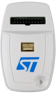
- ST-LINK programmer (v2 or v3)
- 20-pin cable
- ROSSMA IIOT-AMS device
- PC with STM32 ST-LINK Utility installed
System Requirements
Computer requirements:
- Windows 7 SP1 / 10 / 11 (32-bit or 64-bit)
- 512 MB RAM (2 GB recommended)
- 100 MB free disk space
- USB 2.0 port (USB 3.0 supported)
Software
STM32 ST-LINK Utility (version 4.6.0 or higher)
- Download: st.com/st-link-utility
- Size: ~25 MB
- ST-LINK v2 drivers install automatically
Please note: STM32 ST-LINK Utility is deprecated. STMicroelectronics recommends using STM32CubeProgrammer for new projects. However, ST-LINK Utility still works correctly for flashing ROSSMA devices.
Alternative: STM32CubeProgrammer (v2.0+)
Drivers
When connecting the ST-LINK programmer for the first time, Windows will automatically install drivers. If automatic installation fails:
- Download drivers: STSW-LINK009
- Extract archive
- Run
dpinst_amd64.exe(for 64-bit) ordpinst_x86.exe(for 32-bit) - Follow installer instructions
Step-by-Step Instructions
Step 1: Connect Programmer
- Connect ST-LINK programmer to computer via USB
- Connect 20-pin cable to programmer
- Ensure correct orientation: numbering on programmer side (view from top)
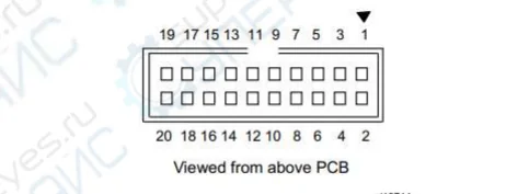
Warning! Incorrect connection may damage the device.
Step 2: Connect to ROSSMA Switch
- Remove ROSSMA switch cover
- Locate programming connector on motherboard
- Connect 20-pin cable to programming connector
- Ensure secure connection
Step 3: Launch STM32 ST-LINK Utility
- Launch STM32 ST-LINK Utility on computer
- In menu select Target → Connect
- Verify program successfully connected to device
- If connection error occurs - check cable and device power
Step 4: Load Firmware File
- In menu select File → Open file...
- Select firmware file (.hex or .bin) for your device
- Verify correct firmware file selected for your switch model
CRITICAL! Using incorrect firmware file may render device inoperable.
Step 4.5: Verify File Integrity (Recommended)
Tip: Before flashing, it's recommended to verify file checksum to ensure integrity and absence of download corruption.
Method 1: Verification via STM32 ST-LINK Utility
- After opening file, look at status bar at bottom of window
- Check file size - it should match size from documentation
- Start Address should be
0x08000000
Method 2: Checksum Verification via Command Line
Open Windows Command Prompt and execute:
certutil -hashfile pathtofilefirmware.hex SHA256
Example:
certutil -hashfile C:DownloadsROSSMA_v1.5.2.hex SHA256
Program will output file hash. Compare result with checksum from README file or data provided by ROSSMA technical support.
If checksums don't match - file was corrupted during download. Download firmware file again!
Step 5: Program Device
- In menu select Target → Program & Verify...
- In opened window verify parameters:
- Firmware file path
- Start address (usually 0x08000000)
- Options: Verify after programming (recommended)
- Click Start button
- Wait for flashing process to complete
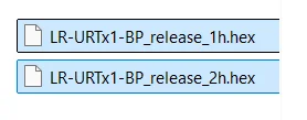
Figure 1. Program & Verify dialog with flashing parameters

Step 6: Verification
- After successful flashing, program will display verification success message
- In menu select Target → Disconnect
- Disconnect programmer from device
- Replace switch cover
- Apply power to device
- Verify device operation
Successful flashing! After verification, device is ready for operation. Check LED indication after powering on.
Troubleshooting
Programmer Won't Connect to PC
Symptoms:
- Programmer not detected in Device Manager
- ST-LINK Utility doesn't see programmer
- LED on programmer not lit
Solutions:
-
Check USB cable and port
- Try different USB port (preferably directly on motherboard, not via hub)
- Try different USB cable
- USB 2.0 ports preferred (fewer compatibility issues)
-
Reinstall ST-LINK drivers
- Open Device Manager (Win+X → Device Manager)
- Find unrecognized device or "STMicroelectronics STLink"
- Right-click → Uninstall device
- Disconnect and reconnect programmer
- Drivers will install automatically
-
Update ST-LINK programmer firmware
- Download STSW-LINK007
- Run STLinkUpgrade.exe
- Click "Device Connect"
- Click "Upgrade" if new version available
Tip: If programmer still not detected, try on another computer to rule out hardware fault.
Cannot Connect to ROSSMA Device
Symptoms:
- ST-LINK Utility shows error when attempting connection
- "Can not connect to target"
- Error 0x8001 or similar
Solutions:
-
Check cable connection to device
- Ensure 20-pin cable correctly oriented
- Verify secure connection (cable should be firmly inserted)
- Check cable for damage
-
Check device power
- Device must be powered (battery connected)
- Battery voltage must be at least 3.0V
- Check LED indication on device
-
Try Connect Under Reset mode
- In ST-LINK Utility: Settings → Reset Mode → "Connect Under Reset"
- This helps if device is in low power mode
-
Check connection settings
- Target → Settings
- Mode: "Normal"
- Reset Mode: "Software system reset"
- Frequency: 4000 kHz (or lower if issues occur)
ST-LINK Error Codes
| Code | Problem | Solution |
|---|---|---|
| 0x8001 | Cannot connect to target device | • Check cable and orientation • Check device power • Try Connect Under Reset |
| 0x8002 | Target device locked (protection) | • Perform Mass Erase via Target menu • WARNING: Will erase all data! |
| 0x8003 | Target device busy | • Close other programs using ST-LINK • Restart ST-LINK Utility |
| 0x8004 | SWIM connection error | • Not applicable to STM32, used for STM8 |
| 0x8005 | No response from target device | • Verify device is powered on • Reduce connection frequency to 950 kHz |
| 0x8007 | Verification error after programming | • Repeat flashing • Check firmware file (checksum) • Perform Full Chip Erase before flashing |
| 0x8009 | Cannot halt core | • Press RESET button on device • Use Hardware Reset instead of Software |
If error not listed in table, take screenshot and contact ROSSMA technical support with full error text.
Programming Error
Symptoms:
- Flashing process starts but aborts with error
- "Programming error"
- Verification fails
Solutions:
-
Verify firmware file integrity
- Use checksum verification (see Step 4.5)
- Download firmware file again from official source
-
Perform Full Chip Erase
- Target → Erase Chip
- Wait for operation to complete
- Repeat flashing
WARNING! Full Chip Erase will delete all information from device memory, including calibration data (if stored in main memory). For ROSSMA devices this is safe, as calibration is stored separately.
-
Ensure correct file is used
- Verify device model
- Check firmware version (must be compatible)
-
Reduce programming speed
- Settings → Frequency → set 950 kHz instead of 4000 kHz
- Slower but more reliable
Flashing Interrupted During Process
Situation: During flashing, power was lost, cable disconnected, or program froze.
DON'T PANIC! Device can be recovered. STM32 microcontroller is protected from bricking.
Recovery steps:
-
DO NOT disconnect programmer and DO NOT remove power
-
If ST-LINK Utility froze:
- Open Task Manager (Ctrl+Shift+Esc)
- End STLinkUtility.exe process
- Launch program again
-
Perform full memory erase:
- Target → Connect (if won't connect, use Connect Under Reset)
- Target → Erase Chip
- Wait for "Erase memory successfully" message
-
Flash device again:
- File → Open file (select correct firmware file)
- Target → Program & Verify
- Must enable "Verify after programming" option
- Start
-
Verify result:
- Verification should complete successfully (100%)
- After disconnecting programmer, device should work
If recovery failed after 2-3 attempts - contact ROSSMA technical support. May require special recovery via SWD debugger.
Device Not Working After Flashing
Symptoms:
- Flashing completed successfully, verification OK
- But device won't turn on or doesn't work correctly
- LEDs don't blink or blink incorrectly
Solutions:
-
Verify firmware version
- Ensure firmware file is intended for your device model
- ROSSMA IIOT-AMS Analog ≠ ROSSMA IIOT-AMS ESD (different firmware!)
-
Check supply voltage
- Voltage should be 3.6V ± 0.3V
- If battery discharged (< 3.0V), replace it
-
Check indication after flashing
Normal indication:
- ACT LED: blinks at transmission interval (e.g., once per 15 minutes)
- LoRa LED: briefly lights up when transmitting data
Error indication:
- Error: blinks once per second → communication module not found
- 3 times - pause - 3 times: cannot register on network
- 5 times - pause - 5 times: error sending data to server
-
Perform settings reset (if available)
- Some models have RESET button
- Press and hold for 3-5 seconds
-
Flash device again
- Perform Full Chip Erase
- Flash again with verification
- Ensure correct file is used
-
Check device configuration
- May require configuration via ROSSMA Configurator
- Check DevEUI, AppEUI, AppKey for LoRaWAN
If device still not working, contact ROSSMA technical support with:
- Device model (exact name)
- Firmware version (file name)
- Device serial number
- Problem description and LED indication
Obtaining Firmware Files
Current firmware files for ROSSMA IIOT-AMS devices available:
- On official website rossma.ru
- By request from technical support
- In Documentation section
Technical Support
If problems occur with flashing, contact:
- Email: info@rossma.ru
- Phone: +7 342 233 93 99
- Telegram: @rossma_ru
Additional information:
Battery Replacement Wiki ↗
Home → Knowledge Base → Battery Replacement
WARNING: Meter-switches are equipped with a non-rechargeable lithium-thionyl chloride (LiSOCl₂) battery ER34615M/T manufactured by Fanso. Attempting to recharge the battery may cause a fire!
When Is Battery Replacement Needed?
Signs That Replacement Is Required
- Battery voltage has dropped to 3.0 V or below
- Intervals between data transmissions have increased
- Device has stopped communicating
- More than 10 years have passed since battery installation
Voltage Monitoring
The device transmits battery voltage data with every communication session. Monitoring is performed via:
- The ROSSMA NETS server web interface
- Any compatible LoRaWAN network server
If the meter-switch is found to be non-functional, first check the battery voltage in the monitoring system.
Battery Lifespan
Dependence on Transmission Interval
| Transmission Interval | 14 Ah Battery | 28 Ah Battery | 126 Ah Battery |
|---|---|---|---|
| 1 min | ~90 days | ~180 days | ~2 years |
| 2 min | ~180 days | ~360 days | ~4 years |
| 10 min | ~300 days | ~2 years | ~7 years |
| 1 hour | ~3 years 150 days | ~10 years* | ~10 years* |
| 24 hours | ~10 years* | ~10 years* | ~10 years* |
* The maximum lifespan of lithium-thionyl chloride batteries is limited to 10 years due to natural self-discharge, regardless of capacity.
Data Packet Count
| Battery Capacity | Maximum Number of Packets |
|---|---|
| 14 Ah | 40,000 ± 10% |
| 28 Ah | 80,000 ± 10% |
| 126 Ah | 360,000 ± 10% |
Replacement Instructions
IMPORTANT: Battery replacement must be performed by qualified personnel. Consumer repair and maintenance of the meter-switch is not permitted!
Replacement Procedure
-
Opening the enclosure:
- Unscrew the screws (4 pcs.) securing the lid to the enclosure base
- Carefully remove the lid without damaging the silicone gasket
-
Disconnecting the old battery:
- Disconnect the battery connector from the circuit board
- Unscrew the screw securing the bracket inside the enclosure
- Remove the battery cell and bracket from the enclosure
-
Installing the new battery:
- Place the new ER34615M/T (Fanso) battery cell into the enclosure
- Place the bracket on the battery cell and secure it with the screw
- Connect the battery connector to the circuit board (observe polarity!)
-
Checking functionality:
- Verify LED indication (LEDs should blink upon power-up)
- Wait for the device to establish communication
- Check data on the ROSSMA NETS server
-
Closing the enclosure:
- Check the condition of the silicone gasket (replace if necessary)
- Install the lid and tighten the screws in a cross pattern
For explosion-proof versions: Ensure the absence of an explosive atmosphere before opening the enclosure!
Battery Technical Specifications
| Parameter | Value |
|---|---|
| Type | ER34615M/T |
| Manufacturer | Fanso |
| Voltage | 3.6 V |
| Capacity | 14,000 mAh (14 Ah) |
| Form Factor | D (34.2 mm × 61.5 mm) |
| Chemistry | LiSOCl₂ (lithium-thionyl chloride) |
| Temperature Range | -55°C to +85°C |
CRITICAL: Use only a non-rechargeable lithium-thionyl chloride battery cell ER34615M/T manufactured by FANSO. Using other batteries may result in malfunction, warranty void, or fire!
Capacity Variants
14 Ah (Standard)
- Device enclosure dimensions: 80×75×55 mm / 82×80×55 mm
- Application: Standard conditions, frequent data transmission
- Devices: ANALOG, ESD, PULSE, 1-WIRE, VPM, TILT
28 Ah (Compact Extended Capacity)
- Device enclosure dimensions: 80×75×55 mm
- Application: Compact solution with extended battery life
- Devices: ANALOG Ex 28 Ah
126 Ah (Extended Capacity)
- Device enclosure dimensions: 260×160×90 mm
- Application: Hard-to-reach locations, infrequent replacement
- Devices: ANALOG Ex 126 Ah, ANALOG X4 126 Ah
Battery Disposal
ENVIRONMENTAL: Lithium-thionyl chloride batteries are classified as hazardous waste. Do not dispose of them in household waste!
Disposal guidelines:
- Return spent batteries to specialized collection points
- Store used batteries in a dry, cool place until disposal
- Do not allow short-circuiting of the contacts
Related Pages
- Device Installation — mounting instructions
- Communication Protocols — control commands
- Battery Calculator — lifespan calculation
- ROSSMA Configurator — device configuration
- Device Catalog — all ROSSMA IIoT-AMS models
ROSSMA Device Installation Wiki ↗
Home → Knowledge Base → Device Installation
General Requirements
IMPORTANT: Installation and configuration of meter-switches must be performed by qualified personnel.
Installation Site Requirements
When selecting an installation location for the meter-switch, consider:
-
Device version compatibility with installation zone:
- General industrial version — for normal conditions
- Explosion-proof version (Ex) — for hazardous areas
-
Protection from aggressive environments:
- Exposure of aggressive chemicals to the housing is not permitted
- Exposure of aggressive environment to internal PCB elements is not permitted
-
Radio communication conditions:
- Reliable LoRaWAN network coverage at installation site
- Absence of significant shielding obstacles (thick metal walls, underground rooms)
Mounting Methods
Mounting options:
- On vertical or horizontal surface using mounting plate
- On DIN rail using adapter (purchased separately)
- On pipe or other structure using clamps
- Directly to sensor
- With cable ties to support structure
Battery-Powered Device Installation
General Installation Procedure
-
Preparation:
- Remove top cover (unscrew 4 screws)
- IMPORTANT: Disconnect battery before connecting cables
-
Equipment connection:
- Prepare cable of required length (KSPV 2×0.5 recommended)
- Strip cable on both ends (approximately 5 mm)
- Connect cable to terminals according to device diagram
- Route cable through cable gland
-
Power connection:
- Connect battery connector to board connector
- Check LED indication
-
Closing the housing:
- Ensure silicone gasket is properly installed
- Secure cover with screws, tightening in cross pattern
Explosion-proof version: When installing in hazardous areas, follow PUE Chapter 7.3 "Electrical installations in explosive areas" and GOST 31610.7-2012.
220V Powered Device Installation (MODBUS)
Installation Procedure
Step 1: Prepare installation site
- Select location protected from direct sunlight
- Ensure access for maintenance
- Install DIN rail (if using rail mounting)
Step 2: Mount the device
- On DIN rail: snap adapter onto rail until it clicks
- On wall: use mounting brackets and 4mm screws
- In hazardous area: use only explosion-proof enclosure
Step 3: Connect power
- Turn off 220V power at main circuit breaker
- Connect phase (L) and neutral (N) to power terminals
- Connect ground (PE) to housing
- Verify connections with multimeter
DANGER: Work with 220V voltage must be performed only by qualified electrician!
Step 4: Connect RS-485 (for MODBUS)
- Connect A+, B-, GND wires according to diagram
- Use 120 Ohm terminators at line ends (for lengths >50m)
- Ensure correct polarity (A+ to A+, B- to

Step 5: Verify connection
- Apply 220V power
- Wait for PWR indicator to light up
- Check ACT indicator blinking (data exchange with devices)
- Ensure Err is not constantly lit
Cable Requirements
For RS-485 (MODBUS)
Recommended cable:
- Shielded twisted pair (STP)
- Cross-section: 0.5-0.75 mm² (AWG 20-18)
- Characteristic impedance: 120 Ohm
- Shield grounded on one side
Cable examples:
- KVVG 2×0.75 (for industrial conditions)
- KVBbShv 1×2×0.75 (for hazardous areas)
- Cat5e/Cat6 (for short distances <50m)
Maximum RS-485 bus length: 1200 meters
For 1-Wire
Recommended cable:
- Twisted pair (UTP Cat5 or higher)
- Shielded cable for industrial conditions
- Cross-section: 0.5-0.75 mm²
Maximum line length: 100 meters
For Analog Sensors (4-20 mA)
Recommended cable:
- KSPV 2×0.5
- Shielded twisted pair for long lines
Device Indication
Battery-Powered Devices (ANALOG, ESD, PULSE, 1-WIRE, VPM)
| Indicator | Description |
|---|---|
| ACT (Activity) | Blinks when receiving data / registering events |
| LoRa | Blinks during LoRaWAN transmission/reception |
| Status blinks periodically | Data transmission to server in progress |
| Error blinks 1 time/sec | Communication module not detected |
| Error blinks 3-3 | Unable to register on network |
| Error blinks 5-5 | Data transmission error |
MODBUS Devices (220V)
| Indicator | Description |
|---|---|
| PWR | Power supplied |
| ACT | MODBUS protocol data exchange |
| LoRa | LoRaWAN data transmission/reception |
| Err | MODBUS protocol exchange error |
| NET | NB-IoT network connection |
| Success | Successful NB-IoT transmission |
Control Buttons
| Button | Function |
|---|---|
| RESET | Device restart |
| Measure and Send | Forced measurement and data transmission (ANALOG) |
Related Pages
- Battery Replacement — battery replacement instructions
- Communication Protocols — control commands and data formats
- ROSSMA Configurator — device configuration
- Quick Start — first network connection
- Device Catalog — all ROSSMA IIoT-AMS models
Troubleshooting Wiki ↗
Home → Knowledge Base → Troubleshooting
A guide to diagnosing and resolving common issues with ROSSMA IIoT-AMS devices.
General Issues
Device Does Not Communicate
Possible causes:
- Battery discharged
- No LoRaWAN/NB-IoT coverage
- Incorrect activation settings (ABP/OTAA)
- Signal shielding (metal enclosure, basement)
- Device not registered on the server
Solution:
- Check battery voltage via the ROSSMA NETS server (should be >3.0 V)
- Check the signal level RSSI (should be > -120 dBm)
- Ensure that activation keys are entered correctly
- Move the device closer to a window or base station
- Verify device registration in ROSSMA NETS
PWR Indicator Not Lit (for externally powered devices)
Possible causes:
- No 220 V power at the L/N terminals
- Built-in fuse has blown
- Incorrect phase and neutral connection
Solution:
- Check for 220 V with a multimeter
- Check the condition of the input circuit breaker
- Ensure correct L and N connections
- Contact the ROSSMA service center
Battery Drains Quickly
Possible causes:
- Too frequent communication intervals
- Transmitter power too high
- Poor network coverage (device spends energy on retransmissions)
- Faulty sensor or input
Solution:
- Increase the data transmission interval (recommended: no more than once per hour)
- Reduce transmitter power in settings (if coverage is adequate)
- Improve reception conditions or use a repeater
- Check the connected sensors for faults
Reference: Estimated battery life — up to 10 years with 1 transmission per day. See Battery Replacement for lifespan tables.
LED Indication
Normal operation (autonomous devices):
- LED blinks during communication (at the configured interval)
- ACT LED blinks when data is received from sensors
Problems:
- Both LEDs are off — power issue (battery discharged or disconnected)
- Communication LED does not blink for an extended period — no network connection
- Error LED blinks once per second — communication module not detected
- Error LED blinks 3 times – pause – 3 times — device cannot register on the network
- Error LED blinks 5 times – pause – 5 times — data transmission error
1-Wire Sensor Issues
Sensor Not Detected
Possible causes:
- Incorrect connection polarity
- Break in the data line (DQ)
- Faulty or incompatible sensor
- Missing pull-up resistor (for multiple sensors)
Solution:
- Check polarity: GND to GND, DQ to DQ, VDD to VCC
- Check wire continuity with a multimeter
- Replace with a known working sensor
- Install a 4.7 kΩ resistor between DQ and VCC
Incorrect Temperature Readings
Possible causes:
- Sensor installed in a location with poor heat exchange
- Sensor near a heat source
- Incorrect sensor calibration
- Sensor damaged
Solution:
- Move the sensor to a location with better heat exchange
- Isolate the sensor from direct sunlight and heat sources
- Test the sensor in a glass of ice water (should read ~0°C)
- Replace the sensor if readings are incorrect
Multiple Sensors — Only One Works
Possible causes:
- Missing 4.7 kΩ pull-up resistor
- Address conflict (ROM collision)
- Maximum bus length exceeded
- Too many sensors on one line
Solution:
- Install a 4.7 kΩ resistor between DQ and VCC
- Use quality cable (twisted pair)
- Reduce line length (max 100 m)
- Reduce the number of sensors (recommended up to 10)
Pulse Input Issues (PULSE)
Pulses Not Registered
Possible causes:
- Incorrect connection
- Faulty input
- Incompatible signal type
Solution:
- Check the wiring diagram and polarity
- Ensure the signal matches the input type
- Contact the ROSSMA service center
Pulses Are Lost
Possible causes:
- Signal frequency too high
- Contact bounce
Solution:
- Ensure the frequency does not exceed 300 Hz or use a divider
- Use a counter with debounce protection or add an RC circuit
Incorrect Counter Readings
Possible causes:
- Interference on the line
- Noise from power cables
Solution:
- Check cable shielding, use twisted pair
- Use galvanically isolated inputs
- Route signal cables separately from power cables
Modbus Device Issues
ERR Indicator Constantly Lit
Possible causes:
- No response from Modbus devices (incorrect Slave ID)
- Connection error A+/B- (polarity reversed)
- Incorrect baud rate
- Break in the RS-485 line
- Parity settings mismatch
Solution:
- Verify the Slave ID in the configurator
- Check A+/B- polarity with a multimeter (A+ should be 1-2 V higher than B- in idle state)
- Ensure the baud rate matches the connected devices
- Check RS-485 cable integrity
- Use a Modbus scanner for device diagnostics
- Measure resistance between A+ and B- — should be 120 Ω (with terminators installed)
Modbus Device Not Responding
Possible causes:
- Incorrect Slave ID configuration
- Different baud rates
- No power to the Modbus device
- RS-485 line length exceeded
Solution:
- Use a USB-RS485 adapter and Modbus Poll software to test the device
- Ensure the device Slave ID matches the configuration
- Verify that the baud rate is the same (typically 9600 or 19200)
- Measure line resistance
- Add 120 Ω terminators at both ends of the line
Data Arrives But Is Decoded Incorrectly
Possible causes:
- Wrong data type in the profile (Float instead of Uint16)
- Wrong byte order (Big Endian / Little Endian)
- Incorrect register address
- Scale factor needs to be applied
Solution:
- Study the Modbus device documentation (register map)
- Ensure the data type in the profile matches the device
- Check byte order (ABCD, BADC, CDAB, DCBA)
- Verify scale factors
- Use the Data Decoder to analyze the payload
Utility Meter Issues
Mercury 230 Electricity Meter Not Responding
Solution:
- Ensure the RS-485 interface is activated (see the meter's datasheet)
- Check the network address (factory default — usually 1 or 0)
- Baud rate should be 9600, parity — Even
- Use the Mercury Configurator software to test communication
Energomera CE301 Electricity Meter Not Responding
Solution:
- Verify the meter supports the Modbus RTU protocol
- Default network address — 1
- Baud rate — 9600, parity — Even
- Ensure the correct register map is used (see the datasheet)
SPT-941 Heat Calculator Not Responding
Solution:
- Verify the heat calculator is powered on and operational
- Default address — 1, baud rate — 9600, parity — None
- Ensure firmware with Modbus RTU support is installed
- Use the SPT Configurator software to test communication
VKT-7 Heat Calculator Not Responding
Solution:
- Default address — 247 (must be changed via the device menu)
- Baud rate — 9600, parity — Even
- Activate Modbus RTU mode via the device menu (see the manual)
Relay Issues (DRY CONTACT RELAY)
Relay Does Not Switch (no click heard)
Possible causes:
- No communication with the server (device not receiving the command)
- Faulty relay
- Not registered on the server
Solution:
- Verify the device is registered on the ROSSMA NETS server
- Check the LoRaWAN/NB-IoT signal level (RSSI should be > -120 dBm)
- Send an on/off command via the web interface
- If the relay does not click, contact the service center
Relay Switches But Load Does Not Turn On
Possible causes:
- Break in the load circuit
- Incorrect load connection (wires on wrong terminals)
- Load fuse blown
- Load is faulty
Solution:
- Disconnect 230 V power
- Verify correct load connection to COM and NO terminals
- Check the load wiring integrity
- Check the load itself (lamp, pump, etc.) — it must be functional
- Measure resistance between COM and NO with the relay energized (should be ~0 Ω)
Discrete Inputs Not Responding
Solution for IN1, IN2 (galvanically isolated):
- Check connection polarity: IN1+ to positive, IN1- to negative
- Check wire integrity
- Measure voltage between IN1+ and IN1- (should be 0 V when the contact is open)
Solution for IN3, IN4:
- Verify one wire is connected to IN3/IN4, the other to GND
- Manually short IN3 to GND — the status should change on the server
- Check the sensor contact integrity
Load Turns On But Relay Quickly Turns Off (bouncing)
Possible causes:
- Rated current exceeded (>10 A)
- Short circuit in the load
- Inductive load without a snubber (contact arcing)
Solution:
- Measure the load current with clamp meter (should be <10 A)
- If current >10 A, use an intermediate contactor
- For inductive loads (motors), install an RC snubber:
- Resistor 47–100 Ω, 2 W
- Capacitor 0.1–0.47 µF, 400 V
- Connect in parallel with the contactor coil or motor
Technical Support
For issues not described above, contact ROSSMA technical support:
- Official website: https://rossma.ru
- Email: info@rossma.ru
Before contacting support, prepare: device serial number, problem description, server data screenshots, connection photos (if applicable).
Related Pages
- Device Installation — mounting instructions
- Battery Replacement — battery replacement guide
- Communication Protocols and Commands — control commands
- FAQ — frequently asked questions
- ROSSMA Configurator — device configuration
Can't find a document in your language?
Send a request and we will prepare a translation of the document you need.
Request document →